Wapnö is an integrated dairy farm with its own on-site dairy products processing. Located just outside the city of Halmstad on the west coast of Sweden, Wapnö recently installed an innovative biogas-based energy system. Using only manure as feedstock, the biogas is used to supply the entire Wapnö agri-complex with heat, power and -11 oC cooling. Along with odourless fertiliser and 2 MW energy to spare, it is perhaps the most energy-efficient and environmentally optimal biogas system ever built.

The global demand for meat and dairy products continues to grow at profound rates, especially in the developing world. According to the UN Food and Agriculture Organization (FAO), the per-capita milk consumption in developing countries almost doubled and meat consumption more than tripled between 1980 and 2005.
During the period 1980 to 2010, the global cattle population grew 17 percent to reach 1.4 billion animals. The Consultative Group on International Agricultural Research estimates that by 2050, the global cattle population will have almost doubled to 2.6 billion animals to provide for an estimated human population of 9.7 billion.
Local production
It follows that as animal and human populations increase, so too does the need to increase the production of food, fodder, and feed in an energy efficient and environmentally sustainable way.
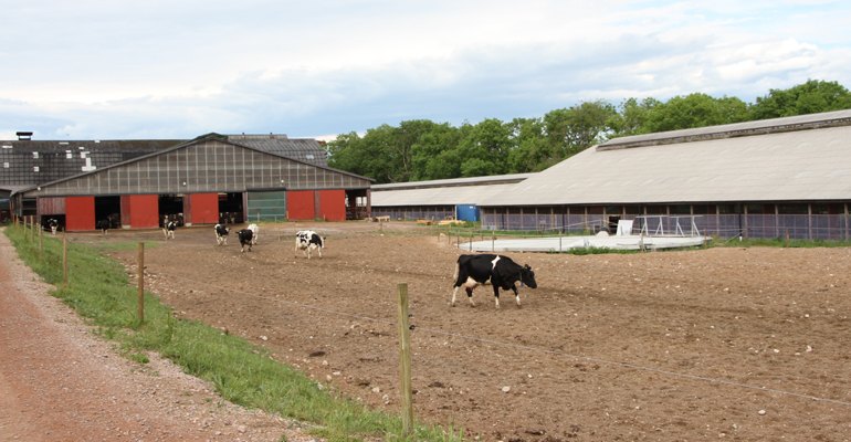
Wapnö’s current contribution to the global cattle population is around 3 300 animals of which 1 300 are milk cows and the rest are calves and heifers. The 2 200 hectare (ha) holding is made up of 1 650 ha arable land, 100 ha pastures, and 450 ha forest, and it is run as a limited company with some 50 employees.
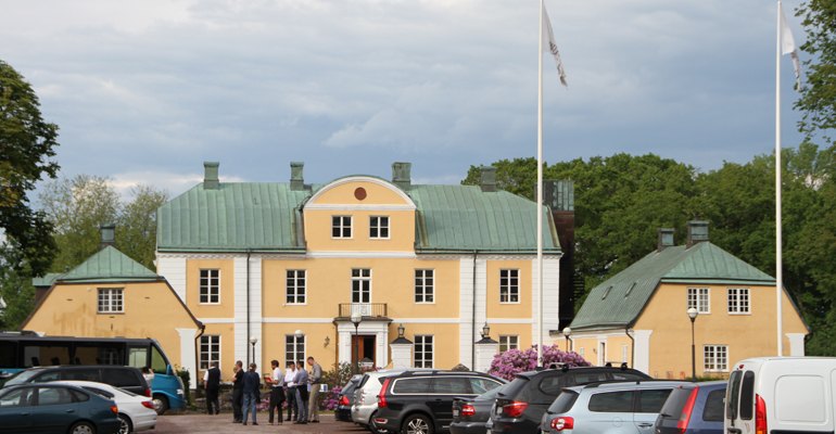
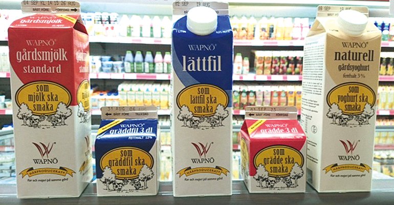
In fact, Wapnö is an agri-business complex that has evolved around its focus on the cow. Today the on-site business operations include milk and associated dairy products that are sold to supermarkets in the region, a 21-bed hotel and conference venue, a restaurant that sources its ingredients, including beef, from the farm, and a “Farmer’s Market” shop for products from the farm. The company has strong local production and sourcing ethos.
According to Wapnö CEO Lennart E. Bengtsson, the primary task for arable production on the farm is to provide feed, fodder, and bedding for the cows, thereafter food production. The animals are kept open range year-round having free access to large sheds with bedding, feed, and water. On an annual basis about 10 000 tonnes of grass and whole crop silage, 3 700 tonnes of grain, and 1 110 tonnes of straw of which 400 tonnes is chopped for bedding is produced.
Energy optimisation
Wapnö’s energy “hoof print” however is very different from any other livestock farm or dairy. In June 2011 a decision was made to invest in an innovative biogas-based energy system to cater to the entire energy needs of its operations, that is cooling, heat, and electricity.
The Danish company Lundsby Bioenergi A/S was given the c. DKK 12 million (≈ EUR 1.61 million) contract to provide the biogas system on the pre-condition that it could commit to a minimum daily biogas output.

Furthermore the only feedstock for the biogas plant that would be made available to achieve this output was going to be residues from the farm, 36 000 tonnes of slurry, 3 000 tonnes of solid manure, and 700 tonnes of feed residues. The plant was commissioned in April 2012.
This is more of a challenge than it sounds. Cattle manure on its own has a relatively low methane yield and long retention time. And we had to ensure a minimum daily biogas yield that would be enough for the downstream energy system, said Karsten Hjorth, Project Manager Lundsby Bioenergi A/S.
From a plant perspective, this is usually compensated by blending a percentage of a crop-based feedstock such as maize silage. However at Wapnö, this is not an option as company policy forbids the use of any purpose-grown feedstock, the arable land has too high a “food value” and is used for food and feed production.
Unconventional
The biogas plant itself is a conventional mesophilic two-stage anaerobic digestion plant with a number of special adaptations and features all designed to make it as energy efficient as possible, in particular with the use of heat.
What makes the Wapnö setup unique for a farm-based biogas plant is that apart from supplying electricity and space heating to the entire complex, the heat is used to supply cooling.
Slurry from the cow sheds is collected and pumped to an insulated buffer tank that is buried at ground level. Manure, bedding material, and feed residues are fed into a Trioliet double-auger stationary feeder mixer using a front-loader.
The lukewarm, 10-20 oC, slurry from the buffer tank and the macerated material from the feeder mixer are fed into an insulated mixer tank where the material is stirred to a homogeneous mass. The mixer tank is also heated as the incoming material from the feeder mixer is cold.

A special feature is that it is heated by using a heat exchanger to capture the heat from the outgoing warm digestate before this goes into storage.
The preheated and mixed material passes a stone separator before being pumped into the 3 800 m3 digester where 70-85 percent of the biogas volume is produced. Here the temperature is increased to around 40 oC by a heat exchanger on a hot water circuit.
The digester also doubles for biogas storage with hydrogen sulphide (H2S) reduction to 100-200 ppm. This enables scheduled stops on downstream equipment such as maintenance services without biogas loss due to flaring or plant shutdown.
From the digester, the still biologically-active material is fed into the 3 800 m3 post-digester unit where the remaining 15-30 percent of the biogas is produced.

From the post-digester, the digestate is fed past the mixer tank via a heat exchanger to extract the heat before going into the digestate storage tank. Solids are separated from the digestate and water is added when it is applied as an odourless organic fertilizer on Wapnö’s fields. The fiberous solids are dried, packed in fertilser bags, and sold as a soil improvement product.
Power and cooling
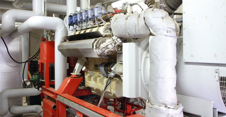
Water is removed from the biogas and the condensate is returned to the mixer tank. The biogas is piped to the combined heat and power gen-set located next door to the dairy some 400 m away from the biogas plant. To keep emissions of nitrogen oxides (NOx) down, a urea-based NOx-reducing agent is used.
The heat from the water-cooled 300 kW capacity rated MAN gas engine gen-set is used as the heat source for the Absorbption Refrigeration Plant (ARP) as it provides a high and stable flow and water temperature, which is important for the overall efficiency for both the engine and the ARP.
The heat in the flue gas is also used. The outgoing engine exhaust has a temperature of 500-600 oC and has two heat exchanger circuits in succession.
The first one is connected to the engine cooling and the ARP circuit to ensure a stable operating temperature. This brings the flue-gas temperature down to around 180 oC. The second flue-gas heat exchanger is connected to the existing hot water network for space heating including the digester.
Other heat pumps that are connected to this network include the engine room to utilize radiant heat from the engine and in the dairy.
By using the heat from the milk the heat pumps installed in the dairy can raise the water temperature from 38 oC to 60 oC to supply the digester with heat if there is no heat in the rest of the system, for instance, a very cold winter’s day.
This is a unique set-up because normally we would use the heat from the gas engine for the digester. It is really exciting as we have enquiries for biogas projects where heat is not needed but cooling is, commented Karsten Hjorth.
Heat to cool
The ARP uses ammonia as the refrigerant medium, can cool down to -11 oC, and supplies all the cooling and refrigeration needed at Wapnö; the dairy production process, cold storage as well as the shop and space cooling on the entire premises. Supplied by Dutch chiller specialists Collibri BV it was developed together with the local heat and cooling installation company Halmstad Kylservice for Wapnö.
The task was to extract as much cooling as possible from the supplied heat. Once the calculations and flows were worked out we had to find a supplier who would build such a chiller that could use 90 oC water and cool to -9 oC, said Jan Thorbjörnsson from Halmstad Kylservice.
An ARP consists of a high-pressure and a low-pressure part and, just as in a conventional compression refrigeration plant (CRP), the refrigerant is liquefied under high pressure in the condenser and evaporated under low pressure in the evaporator.
The ARP absorption cycle
The main components of the solution cycle are the absorber, the desorber, and a liquid pump. The solution cycle uses the ability of water to dissolve ammonia vapour to form a solution. This process takes place in the absorber, which works on the same low-pressure level as the evaporator.

The solution entering the absorber is weak with a low concentration of ammonia and is able to absorb the ammonia vapour coming from the evaporator and dissolve it. The now ammonia-rich solution has a high ammonia concentration and is pumped to the desorber, which works on the same high-pressure level as the condenser.
By heating up the desorber, this concentrated ammonia solution re-separates into ammonia vapour and a weak ammonia solution. The weak solution flows back into the absorber and the ammonia vapour is purified in the rectification column so that nearly pure ammonia vapour enters the condenser, where it is liquefied.
A CRP only needs cooling from the environment for the condenser, in an ARP the amount of environmental cooling is more than double because, in addition to the condenser, the absorber needs cooling as well.
To improve the co-efficient of performance (COP), a term to describe the ratio of useful heat movement per work input, two heat exchangers are installed in an ARP for internal heat exchange: the solution heat exchanger and the condensate cooler.
The key difference between the two refrigeration plant types is that to transport the refrigerant vapour from low pressure to high pressure, a CRP uses electricity to power the compressor, whereas an ARP uses a thermal driven solution cycle, a “thermal compressor“ if you will. The CRP is 100 percent driven by electrical energy for the compressor. The ARP on the other hand only needs 5 percent of its energy as electricity for the pump and 95 percent as thermal energy to heat the desorber, said Jan Thorbjörnsson.
It is this difference that has enabled Wapnö to go from an oil and power purchaser to a combined heat, power, and cooling producer. Not only has the manure-based biogas system fulfilled current cooling, heating, and electricity needs there is room for future expansion.
Roughly 2 MWh per annum of heat is still unused and the biogas plant has additional capacity, up to 4 000 head of cattle. There are plenty of ideas and plans, time will tell what is next for this very cool cow heat and power plant.
Facts
About Wapnö
TECHNOLOGY SUPPLIERS
Biogas plant (incl. CHP genset): Lundsby Bioenergi A/S
Absorbent Refrigeration Plant (ARP): Collibri BV & Halmstad Kylteknik AB
INPUT (per annum):
c. 36 000 tonnes cow slurry
c. 3 000 tonnes cow manure
c. 700 tonnes bedding & feed residues
OUTPUT (per annum):
c. 2 100 000 Nm3 biogas
c. 37 000 digestate ENERGY OUTPUT (per annum):
3 MWh electricity
3 MWh heat to provide 1.7 MWh cooling
1.5 MWh heat for tap water, space heating etc c. 2 MWh heat potential unused
ESTIMATED ENERGY SAVING (per annum):
1.7 MWh electricity from the grid
25 m3 fuel for the grain dryer
13 m3 fuel oil for space heating